
A temperature sensor works on the desk. So does a small display. But when you connect both, add the remaining sensors and route the cables around an enclosure, the readings become intermittent. Before replacing modules, check what changed in the shared connection.
Matching addresses are one possible cause. There is also an electrical one: several individually useful boards can each bring their own pull-up resistors, while every cable and input adds load to the signal lines. Your program may be unchanged, but the circuit it talks through is different.
This note covers what to check before fixing the wiring in place. It is based on the I2C electrical and timing references, not on a multi-module reliability test we have run.
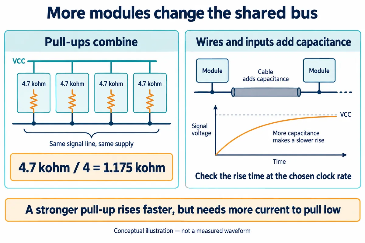
First, identify what each board adds
Start with the exact controller and module revisions, not just the sensor chip names. Look for resistors from SDA and SCL to a supply rail. A breakout-board schematic may show them even when the product description does not. Note their values, the rail they connect to, and any documented jumper for disconnecting them.
The confusion shows up in a November 2024 ESP32 discussion: the author wanted to combine several breakout boards and worried about their accumulated pull-ups, then also asked about identical device addresses. Those are separate checks. Changing an address does not change the resistors on a module.
For example, four 4.7 kohm resistors from the same signal line to the same supply act as about 1.175 kohm. Calculate SDA and SCL separately, and do not apply that simple parallel calculation across different supply voltages or isolated bus segments. The number is an inventory result, not a recommendation to remove a particular resistor.
There is no useful universal answer such as "four modules are safe" or "I2C supports 127 boards." Addresses, device capabilities and the electrical connection all impose limits. I2C also has several modes; the list of modes does not tell you which ones your controller, driver and peripherals can use together. This note is about ordinary Standard-mode and Fast-mode connections.
Understand the two limits before changing resistance
In an ordinary open-drain I2C connection, a device pulls a line low, and the pull-up brings it high when devices release it. Too little resistance can demand more current than a device can sink while keeping a valid low level. Too much resistance can let the line rise too slowly. TI's pull-up calculation note explains these opposing limits.
The note ties the upper resistance limit to bus capacitance and allowable rise time, and the lower limit to supply voltage and the device's low-level drive. So a resistor value copied from a working one-sensor example may need reassessment when the physical assembly changes. Use the actual devices' specifications.
In a TI support discussion about several TMAG5273 boards, the developer first reported only the controller's 2.2 kohm pull-ups. They later found 4.7 kohm resistors on each sensor board and reported that removing the extra pull-ups appeared to restore operation. Their setup also switched sensor power. It is a reminder to inspect the complete circuit, not proof that every multi-board system needs the same change.
Check the edge, not only the clock setting
A clock frequency in software tells you how often communication is meant to happen. It does not show how sharply the voltage actually changes at a sensor connector.
NXP's I2C specification, section 7.1, counts the capacitance of wires, connections and pins together. Its timing tables give maximum rise times of 1000 ns for Standard-mode, 300 ns for Fast-mode and 120 ns for Fast-mode Plus, measured between the 30% and 70% levels. A connection that works at a slower setting has not been checked at the faster one. Read the column for the mode you actually use, and the footnotes in the full specification.
Ask an engineer to look at SDA and SCL with an oscilloscope at the assembled connection, comparing high and low levels and transition timing with the applicable specifications. A logic analyzer is useful for decoded addresses and acknowledgements, but its digital trace does not show the analog voltage shape. Save the setup and measurement conditions with the capture so the result can be reproduced.
You do not need to understand every symbol in the specification's timing diagram to ask for a useful result: identify the failing transaction, show the relevant voltages and timing, and say which requirement is missed.
Change one thing and repeat a meaningful operation
Go back to the smallest arrangement that worked. Record its modules, wiring, clock setting and supplies. Then add one module or cable section at a time, testing the same real operation after each change, for example updating the display while repeatedly reading the sensor. A successful address scan is useful, but it does not show that the complete interaction runs reliably.
If someone changes a pull-up jumper or resistor, record the new effective arrangement and repeat the test. If a lower clock rate helps, keep that observation without assuming it identifies the only cause. Keep checking addresses, supply compatibility, connector mapping and power states; the symptom alone does not tell you which is wrong. A bus fault can also involve more than one problem at once, such as a poor solder joint on an I2C pin plus a configuration error, so keep testing after the first fix.
Decide whether the shared bus still fits the layout
Keep the simplest arrangement that works reliably in the intended assembly. If a long cable or many connected inputs leave too little timing margin, consider a different layout or a deliberately chosen bus buffer or switch. NXP discusses these options in section 7.2 of the same specification; they bring their own timing and electrical conditions. Adding a connector board alone does not isolate the load.
Before building several units, keep a connection record alongside the firmware: exact board revisions, pull-ups and their rails, intended cables, clock rate and the tests performed. That makes a replacement module or wiring change reviewable, and it gives whoever assembles the next prototype more to go on than "it worked on my desk."
The checks proposed here have not yet been run on a physical multi-module prototype; they are the plan for the next bench session.