
Your first sensor works. Now you want a small display, a few buttons and perhaps another sensor on the same prototype. A board with more sockets looks like the obvious next step. It may solve the cabling problem, but the connected devices still need a way to share the connection.
This becomes especially noticeable with two identical sensors. In a February 2025 Blue Robotics discussion, a developer could connect several pressure sensors through a splitter but could not address them separately. They all used the same I2C address. More sockets had not created separate communication channels.
On our bench we ran a smaller version of the same question with a six-socket GraftSense I2C expansion board: connect a five-way button module and an OLED display, then check which addresses answer. This note covers what that showed and when this kind of hub is enough.
Six sockets still share one bus
I2C uses a data line, SDA, and a clock line, SCL. A device's address lets the controller direct a transaction to it. On a passive hub, those lines are shared across the connectors. The hub does not give each socket a new address or a private data path.
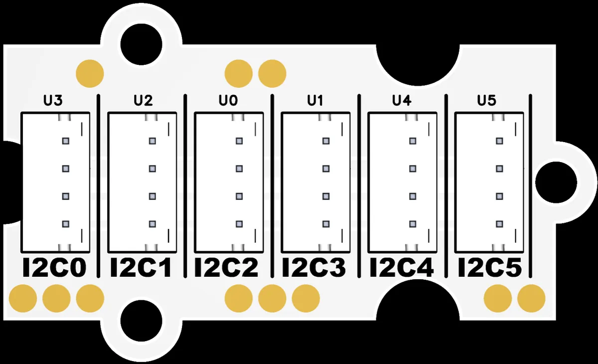
The board's schematic connects all six sockets to the same SDA and SCL nets, and they also share power and ground. There is no channel-selection chip in the circuit. Labels that look like separate links do not make them separate.
One socket connects the hub to the controller, leaving five for modules. Count the upstream cable when deciding whether the board has enough places for your modules. Also read the power requirements: the schematic labels the common rail +5V, but that label does not make every attached signal pin 5V-tolerant. Confirm supply and signal compatibility for the actual boards you plug in.
For comparison, Seeed's TCA9548A multiplexer guide describes a different kind of hub that selects downstream channels. It can separate same-address devices when the software selects the appropriate channel. A passive connector board cannot perform that selection.
The two-module setup
We used a GraftPort-RP2040 controller board, the expansion board, a PCF8574-based five-way button module and a 0.96-inch SSD1306 OLED. The controller uses GPIO4 for SDA and GPIO5 for SCL. Four-wire cables connect the hub and the two peripherals.
| Item | Role in this test |
|---|---|
| GraftPort-RP2040 controller | Runs the MicroPython address scan |
| Passive expansion board | Connects the cables to one shared bus |
| Five-way button module | Expected to answer at 0x20 |
| OLED module | Expected to answer at 0x3D |
Which numbered hub socket each peripheral uses does not matter on this circuit: socket numbering does not select the software address. Keep SDA, SCL, supply and ground aligned, and verify the actual board's supply and signal levels before recreating the setup.
The scan itself needs only machine and time. A driver for reading the buttons or drawing on the OLED is a later step.
Run the scan and read the numbers correctly
The test program waits three seconds after startup, configures I2C0 for a requested 400 kHz clock, and prints the responding addresses once a second. The pin selection is specific to this setup, not a universal connector pinout.
from machine import Pin, I2C
import time

time.sleep(3)
i2c = I2C(id=0, sda=Pin(4), scl=Pin(5), freq=400000)

while True:
    print(i2c.scan())
    time.sleep(1)
The terminal repeatedly printed [32, 61]. Those are decimal numbers: 32 is hexadecimal 0x20, and 61 is 0x3D. They match the two expected addresses. They are not socket numbers, measurements or error codes.
MicroPython's version 1.23 I2C documentation defines the scan as finding addresses that acknowledge. That is what this result establishes. It does not show the OLED drawing a message or the button module reporting individual presses. The next useful test is to perform those two tasks, then run them together.
Decide what to add next
If the new module has a different address and compatible electrical requirements, a passive hub may be enough for a first shared-bus prototype. Add one module at a time and record its address while it is alone. Then reconnect the group. This gives you a useful comparison if an address disappears or a transaction fails.
If two modules have the same address, first check whether the exact device provides an address option. Some boards expose a jumper or pin; others need a startup procedure. If the address is fixed, consider a separate controller bus or a multiplexer. Pick the approach before designing a cable harness around the available sockets.
An address scan cannot count two devices that answer at one address. Nor does moving one of them to another passive hub socket separate them. That is the same distinction behind the pressure-sensor question at the start: the physical connection can be easy while individual access still needs a different arrangement.
Keep the final cable arrangement in the test
Once the modules work together on the desk, repeat the test with the cables and routing planned for the enclosure. I2C needs suitable pull-ups on SDA and SCL, and breakout boards may already include them. Adding modules changes the shared electrical arrangement, and the MicroPython documentation calls out checking that circuitry when communication misbehaves.
Our test gives a clear starting point: two expected addresses responding on one bus. It does not establish a maximum cable length, a tested six-device load or reliable operation inside a finished product. For a small team, the next deliverable should be a module list with addresses, supply requirements and the intended connection layout, followed by tests of the actual functions.