
You are building a handheld field tool, an outdoor activity logger or a device that marks where someone pressed a button. The receiver finally prints latitude and longitude. That is a useful milestone, but the next question is what the user can safely assume when those numbers appear on the screen.
A location can be missing, out of date or poorly received while the rest of the device appears to work normally. Before putting the electronics in a case, make those states visible. On our bench we connected an Air530Z GNSS receiver on a GraftSense carrier, with a ceramic patch antenna, to a Raspberry Pi Pico (RP2040) running MicroPython, and kept both the startup screens and the raw satellite messages behind the displayed result.
Decide what the location is for
A field note taken at a walking stop has different needs from a continuously updated route. Start with the action: does the user need to mark an event, see an approximate place, or record movement? That decision sets how long the device can wait, how old a position may be, and what feedback it gives when reception disappears.
Keep a simple rule for the first build: an event receives a location only when the receiver reports a valid, sufficiently recent fix. If it cannot, save the event with an explicit "location unavailable" state or ask the user to wait. Choose the age limit for the intended activity instead of hiding it inside the software.
Establish the outdoor baseline
We used UART0 at 9600 baud: GP16 transmits and GP17 receives. The carrier's MTX and MRX labels refer to the controller side, so GP16 connects to MTX and GP17 to MRX. Do not apply that naming rule to a different breakout without checking its documentation.
The carrier accepts a 5 V supply, while the Air530Z itself runs from a lower range (2.7 to 3.6 V in the manufacturer's reference). Keep those two power connections distinct, and check against the schematic for your exact carrier revision, not a similar board from another vendor.
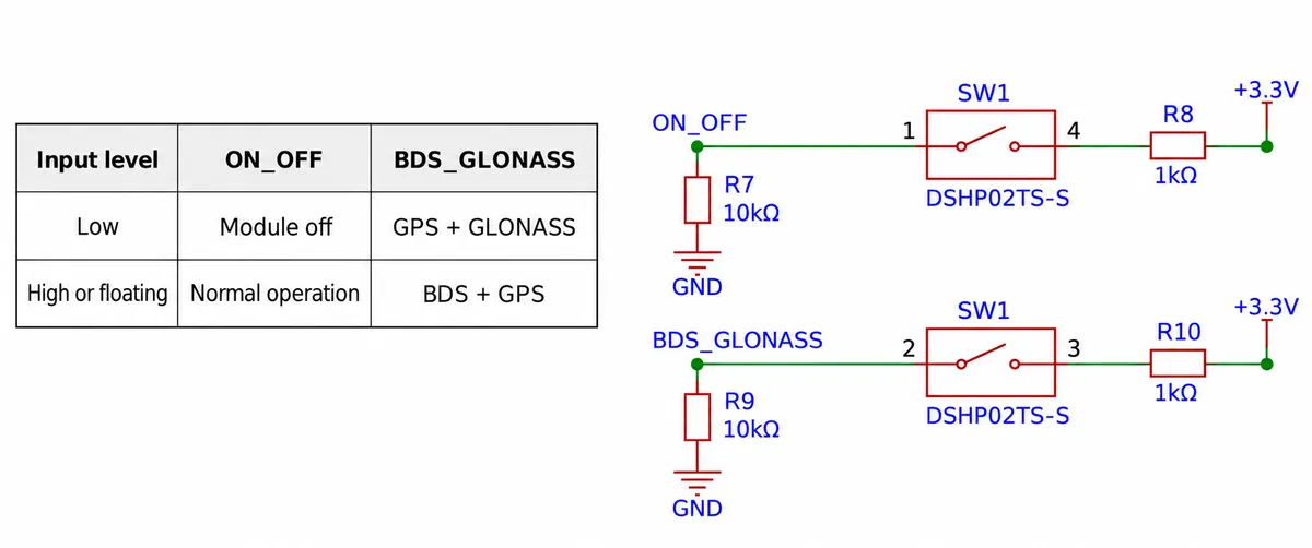
Change those switches with power removed, then restart. Begin in an open outdoor location, with the antenna and cable visible, so that a closed case is not another unknown during the first test.
Our program waited three seconds at startup, created the receiver object on the UART and read it once per loop, printing longitude, latitude, altitude, time and satellite count. The driver we used is a community MicroPython driver by ben0i0d; its header specifies CC BY-NC 4.0, so check the license before it goes anywhere near a commercial product. Keep a raw-message capture alongside the interpreted values. It gives you something concrete to inspect when the display and the receiver disagree.
Read the startup sequence, including the errors
In the first recorded screen, coordinates and time were absent. The second had a time value but still no coordinates. That distinction belongs in the interface: receiving time does not mean the device has a usable position.
A later screen reported a position with an altitude around 162 m, and it also contained list index out of range errors. Both observations matter: the setup did obtain position data, and its parsing path still needs work before unattended use.
One GGA message from that run reported fix quality 1, nine satellites used, HDOP 2.8 and altitude 162.6 m, along with UTC time and a position in degrees-and-minutes notation. HDOP describes satellite geometry; it is not a distance error in meters. To convert a latitude field such as ddmm.mmmmm, take the degrees and add the minutes divided by 60; longitude uses three degree digits. Get this wrong and the marker lands far from where the device is.
The screen showed a satellite count of three, which is not evidence that three satellites are enough for this product. When we replayed the recorded sentences through the parser in software, the GGA count of nine was overwritten by a later GSA sentence listing three satellites for one system. The same replay reproduced the index error on a recorded GSV sentence. These are parser observations, not a new radio test.
Keep fresh data separate from remembered data
UART delivers a stream of bytes, and a read can end halfway through a sentence. The parser we used split each received chunk immediately; replaying a valid GGA sentence in two pieces failed to recover its position. An integration-ready version needs to keep incomplete bytes until the line is complete, validate the checksum and fields, and only then update the message record.
It also needs to keep the time of the last accepted position. A new satellite-status message should not make an old coordinate look new. The driver's read result did not expose a complete freshness and fix-validity decision, so the application has to add that before using a coordinate to mark an event.
This matters outside bench demos. In an Esri Field Maps discussion, staff describe changing the position marker and showing its last update when a location becomes stale. A small handheld device can use simpler wording: "searching," "position ready," or "last position from 40 seconds ago."
The manufacturer's FAQ describes another source of delay: sending too many NMEA sentences over the default 9600-baud link can leave messages queued. Its remedies are a correctly configured faster link or fewer unnecessary sentences. The configuration helpers in the driver we used did not consistently match the manual's command encoding, so do not assume a function named set_baudrate() has changed both ends of the link. Check the exact command and the received output first.
Treat antenna placement as part of the case design
The antenna needs a useful view of the sky in the orientation people will actually hold or carry the product. Reserve space for it early. Compare the open assembly with the proposed case, battery, display and cables in their intended positions, with the rest of the electronics running.
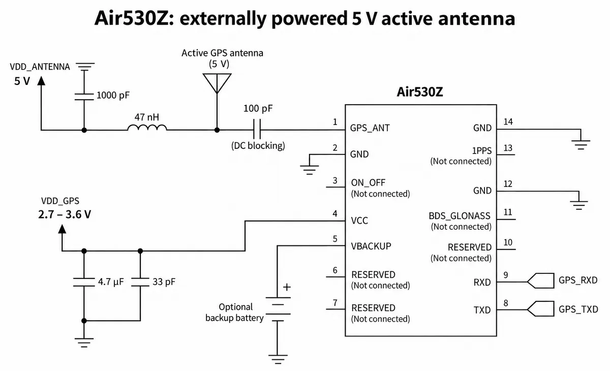
Passive and active antennas have different connection requirements. The manufacturer's reference for a 5 V active antenna feeds it through its own supply path and blocks DC before the receiver input. We have not validated this circuit on an assembled prototype; it explains why the antenna choice belongs in the electrical design, not the accessories list.
For the first enclosure comparison, record the startup condition, time to an accepted fix, message timestamps, and behavior after moving into and back out of poor reception. Repeat with the device in the same place and orientation. We have not yet run that comparison or measured battery life.
The manufacturer's 2 m horizontal figure also has a specific meaning: it comes from an open-sky, 24-hour test reported as 50% CEP, a statistical measure. It does not mean every reading is within 2 m. The startup times are likewise averages under stated conditions (ten trials with more than six satellites at a given signal strength), not deadlines every user will see.
Check the map before blaming the receiver
Pasting converted coordinates into a map is a natural sanity check, but one marker is not an accuracy test. First verify latitude versus longitude, the degree-minute conversion and the coordinate system the map service expects. Some map services use their own coordinate systems, and a mismatch moves the marker even when the serial parsing is correct. For an accuracy comparison, use a known reference point and a documented transformation, and keep multiple observations rather than one good-looking screenshot.
For a first prototype in users' hands, the useful deliverable is a device that clearly says when it knows its position, records events with their actual location status, and recovers predictably after losing reception. That gives you a basis for choosing the enclosure, the power strategy and the next field test.