
An interactive prototype starts with one status light. Then the panel grows: several illuminated buttons, a brighter indicator behind a diffuser, perhaps a row of lights showing progress. A controller setting labeled "2 mA" or "12 mA" can look like a convenient way to choose each light's current. On RP2040, that is not what it does.
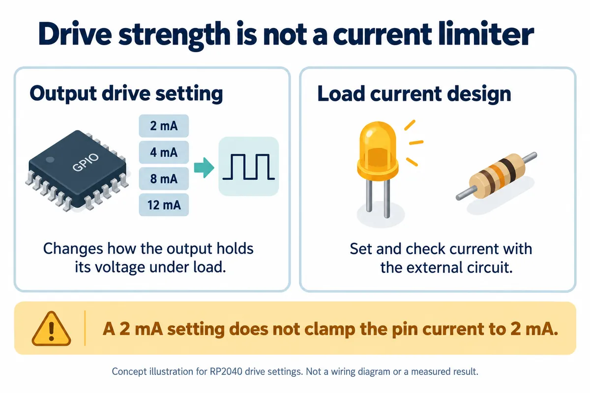
The distinction matters when a breadboard becomes a repeatable build. The external load determines the current together with the output circuit. A drive-strength setting changes the output's ability to hold its voltage under that load; it does not replace the circuit that controls LED current.
Read the setting as part of an output specification
A pad is the electrical interface between the controller's internal logic and the external pin. On RP2040 its output stage has several controls: the value to send, whether the output is enabled, drive strength and slew rate. They describe different aspects of the pin's behavior.
It is easy to describe drive strength loosely as "selecting an output current." The RP2040 datasheet, section 5.5.3.5, is more precise: the nominal 2, 4, 8 and 12 mA modes are not hard current limits. As load current increases, a high output's voltage falls; its specified high voltage is tied to defined loading conditions. The datasheet also requires checking aggregate source and sink currents across the chip, not only one pin.
Imagine that the output is supposed to tell another device "high." The receiving device needs a voltage it can recognize reliably. If the load pulls the output voltage down too far, the program may still be writing a logical one while the physical signal no longer meets the receiver's requirement. That is why output voltage under load belongs in the specification.
The datasheet's typical current-versus-voltage curves illustrate this behavior. They are not a guarantee that every part will tolerate the same extra load, and they are not a recipe for operating beyond the specified conditions. A bright LED on one development board is not a substitute for checking the design that will be repeated.
Do not remove the current-control component because the LED lights
A Raspberry Pi forum question from August 4, 2023 asks this directly: could the author omit an LED's series resistor by selecting the 2 mA drive setting? The replies distinguish drive strength from current limiting. The question is useful because it exposes an easy mistake before it becomes a copied circuit.
For a simple indicator, the external current control commonly includes a series resistor; a dedicated LED driver is another option when the application needs it. A finished module may already contain these parts. Identify what is on the module before adding, removing or duplicating components. Choosing their values requires the actual LED, supply and controller specifications, not the number printed beside the software setting.
In the pad's output path, "output data" selects the logical state, "output enable" determines whether the output driver is active, and "drive strength" configures that driver. The drive-strength control is two bits wide; that is a control width, not a measured load current. None of those settings turns the pin into a regulated supply for an arbitrary load.
The Pico SDK's GPIO API exposes drive strength and slew rate separately. The former selects among the nominal drive modes; the latter concerns transitions. An available register setting is not evidence that the default should always be replaced with the strongest option. Choose settings against the connected circuit and the signal it needs.
Check the complete panel, not only one illuminated button
For a customer-facing control panel, start with the intended visual job: which lights can be on together, whether they are indicators or illumination, and how they will be viewed through the case. A diffuser that looks good mechanically may prompt a request for more brightness. Resolve that request with the LED and driver design instead of assuming firmware can supply unlimited extra current.
Have the engineering test record include the all-on condition as well as a single light:
- the actual current and output voltage with every light that can be on together switched on;
- supply behavior with the other prototype functions running;
- if PWM is used for dimming, the on-state loading as well as average brightness.
These are proposed checks for your assembled design; we have not recorded such measurements for a specific panel here.
A separate driver can keep the controller's job focused on commanding the lights while another circuit handles their load. Whether that is necessary depends on the panel, the exact hardware and the operating conditions. This note does not select a driver or certify a directly connected arrangement.
Put the electrical assumption in the handover
This note uses RP2040's published output specifications. Do not carry those limits over to RP2350 or to a Raspberry Pi Linux computer; record the actual controller and carrier revision before checking the relevant electrical tables.
For the next prototype build, keep the LED or module identity, current-control arrangement, pin assignments and intended simultaneous states together, and add the measured results when available. That prevents a later developer from seeing "2 mA" in a configuration file and assuming the hardware no longer needs its current-control parts. The useful next decision is how to drive the actual panel reliably, not which software number sounds strongest.