
You connect a sensor or display to your prototype, open a serial terminal and see characters arrive. That feels close to success, until none of them make sense. Before replacing the module or rewriting its driver, find out whether the wrong bytes arrived or the right bytes were displayed incorrectly. Those problems need different fixes.
This note is for a team bringing up a serial connection between modules. It is a proposed diagnostic sequence based on how UART framing and clocking work, not a record of a controlled test on a faulty link.
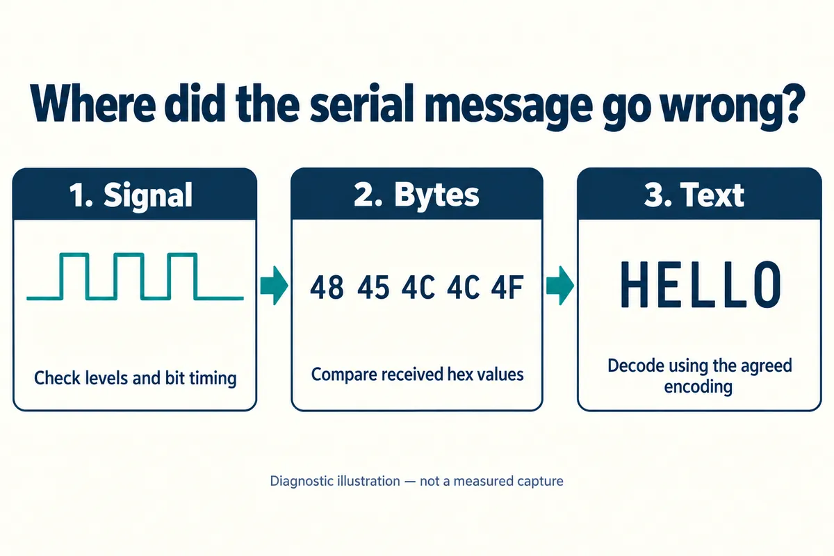
First establish what should arrive
Ask the module supplier for one small, known response, its raw byte values and the settings needed to request it. A terminal full of symbols is normal if the device sends binary measurements rather than text. For a link you control, plain ASCII such as HELLO gives five unambiguous expected bytes: 48 45 4C 4C 4F in hexadecimal.
Compare those values before decoding them. If they match but the terminal shows the text wrongly, look at its display mode or character encoding. If they differ, changing fonts or using a more forgiving decoder will not repair the communication. Keep the raw bytes in the fault report.
Terminal encoding really does cause some of these reports: a module can send correct non-ASCII text that a terminal without the matching encoding shows as noise. That is one possible cause, not the explanation for every garbled output. Python's Unicode explanation describes why the same bytes must be read using the intended encoding.
Match the whole serial format
The familiar setting 115200 8N1 contains several choices: 115200 baud, eight data bits, no parity and one stop bit. Record the complete setting at both ends, including flow control if it is used. Matching only the first number leaves room for a mismatch.
Each UART character is a small frame: a start bit, data bits sent least-significant bit first, an optional parity bit and one or two stop bits. That frame is what the receiver must recognize before the application can interpret a sensor message. The MicroPython UART reference documents the configurable fields and notes that supported combinations depend on the port.
Bit order and byte order are separate ideas. Sending bits least-significant first within a character does not determine the order of bytes in a multibyte sensor value, and it is not the same thing as "little-endian" data. Once raw bytes arrive correctly, interpret values from the module's message specification.
Wiring is another question. Confirm the module's electrical interface, permitted signal levels, common reference and TX/RX connections against its documentation. A connector labeled "serial" does not mean it is compatible with the controller's logic-level UART. Check that before connecting unfamiliar hardware.
If the settings agree, check the timing that reaches the pin
A baud-rate setting is a request to hardware. The UART derives its timing from a clock and a divider; on the RP2040 that divider has a 16-bit integer part and a six-bit fractional part. Most MicroPython projects should let the driver set these registers. The useful question is whether a later clock change invalidated that configuration.
The RP2 quick reference warns that changing the peripheral frequency changes the baud rate of existing UART instances and may require reconfiguring them. If a link works at startup but fails after another part of the program runs, record the firmware version and the clock setup.
If the cause is still unclear, capture the actual line with suitable test equipment. With a repeating 0x55 test pattern, adjacent data bits alternate, so the bit interval is easy to read: nominally about 8.68 microseconds at 115200 baud, or 104.17 microseconds at 9600 baud. These are calculated reference values, not measurements of a prototype. Check both directions and the analyzer's decoding settings; an arbitrary pulse can span several bits.
Stop changing UART settings once the bytes are right
A recent robot-arm builder's discussion shows the next boundary. The servos worked through a USB interface but not from the builder's STM32 program. The visible follow-up says the checksum calculation was wrong; nothing in it points to a baud-rate fault. It is one recent individual example, not a measured trend.
For your next integration review, bring a short record: the exact module and firmware, both ends' settings, the expected bytes, the captured bytes and when the failure occurs. Add a waveform if timing is in doubt. That is enough to decide whether the next task is electrical checking, UART configuration, text decoding or message parsing, without changing all four at once.