
If you are designing a small desk light or an illuminated object, getting an LED to turn on is a satisfying first step. The next question is more practical: will it give the right light, at a useful brightness, once it sits inside the shape people will use?
On our bench we drove a GraftSense module that pairs a single white power LED with an OC7140 constant-current driver, switched and dimmed from a GraftPort-RP2040 board. It worked. Following the setup closely helps separate three decisions: how much current the LED gets, how the user changes brightness, and where the heat goes.
The same questions trip up other builders. In a September 2026 r/AskElectronics thread, someone replacing an acrylic backlight could not reconcile simulated current with the intended LED circuit, and later traced it to a pin-mapping error in the simulation. Understand the circuit you are controlling before treating a brightness setting as a finished lighting design.
Let the driver carry the LED current
The microcontroller pin supplies only a control signal. The LED's operating current comes through the module's power circuit. Keeping those jobs separate is what lets software dim a power LED without a GPIO pin powering it.
The OC7140 is a linear constant-current driver. It adjusts an internal transistor to hold the current set by a small sense resistor. PWM (pulse-width modulation) switches that regulated output on and off quickly; the fraction of time it is on sets the average.
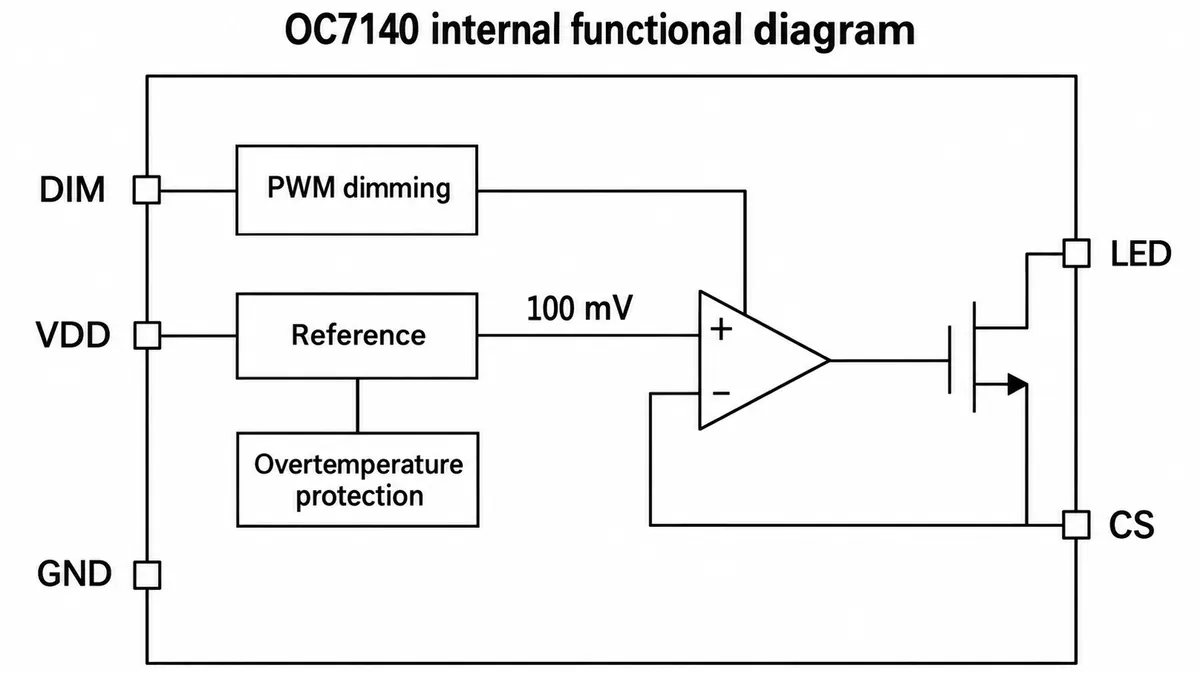
The module uses a 0.300 ohm sense resistor. With the manufacturer's nominal 100 mV reference:
Nominal current while enabled = 0.100 V / 0.300 ohm
                             = 0.333 A (333 mA)
One of our early notes wrote this as 0.333 mA, a thousandfold unit error worth watching for. It is a nominal setpoint, not a current we measured. At 50% PWM duty the ideal average is about half, while the current during each on-pulse stays near the setpoint. Optical and perceived brightness need their own checks.
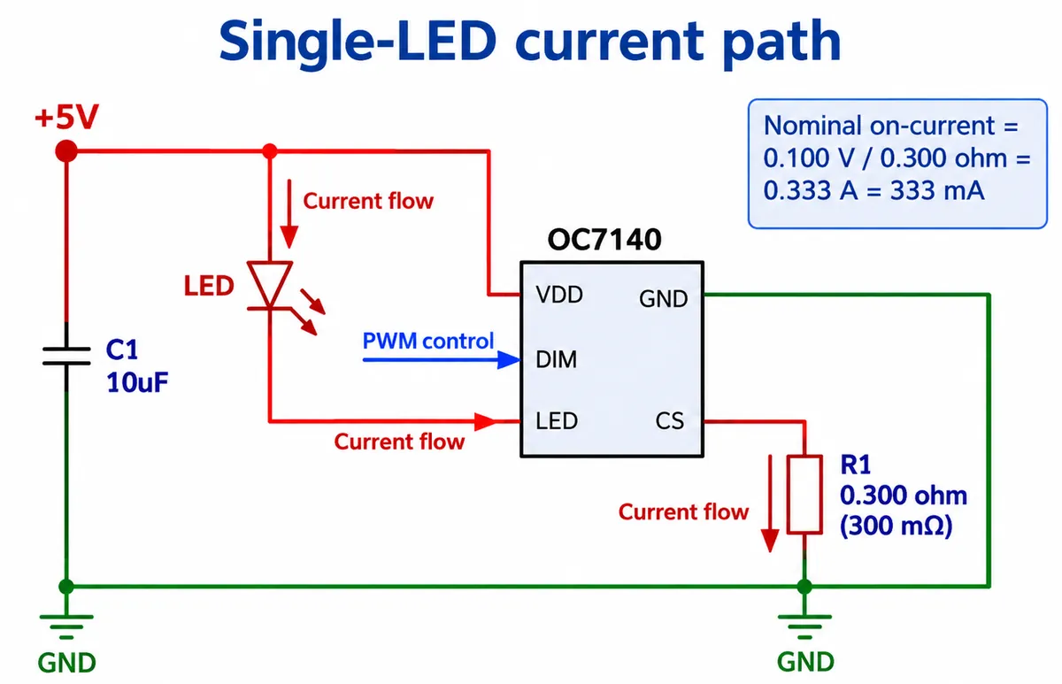
The project files had revision differences, including LED and exposed-pad notes. Resolve them against the datasheets and a reviewed board design before reproducing the PCB.
Connect the control signal, then verify which pin it reaches
The module connects through a four-wire digital connector: GND, VCC, an unused position, and a signal labeled DOUT. Despite the name, in this use DOUT carries a signal into the driver's DIM input.
Our wiring table said GP6, while our program created the LED on pin 14. Do not assume the two are interchangeable; trace the connector to the actual GPIO on your board revision.
Check the control voltage too. The OC7140 datasheet requires a DIM high level of at least 0.7 × VDD, which is 3.5 V when the driver runs from 5 V. A nominal 3.3 V RP2040 output is below that guaranteed threshold. Our module responded anyway, but a repeatable design needs a verified logic interface, such as level translation, rather than hoping every unit behaves the same.
The switching and dimming test
Our driver package exposed on, off, toggle and brightness methods. The test waited three seconds, turned the LED fully on for four seconds, off for four, toggled it on, then raised brightness on a 0 to 1023 scale in steps of 2, pausing half a second per step. That ramp alone takes about 256 seconds; our short video clip of the board switching and changing brightness covered only part of it.
The terminal messages report what the program requested. The driver's state query returns a software flag, not whether light came out. Camera exposure also means a video cannot serve as a brightness or flicker measurement.
For a new experiment, this example uses MicroPython's PWM interface directly. It tries three modest duty settings and always returns the output to off. Set DIM_PIN only after checking the GPIO and the logic-level interface.
from machine import Pin, PWM
import time

DIM_PIN = None  # set to the GPIO verified on your board
if not isinstance(DIM_PIN, int) or isinstance(DIM_PIN, bool):
    raise ValueError("Set DIM_PIN after checking wiring and logic levels")

control = Pin(DIM_PIN, Pin.OUT, value=0)
pwm = PWM(control, freq=1000, duty_u16=0)
try:
    for percent in (5, 10, 25):
        pwm.duty_u16(round(65535 * percent / 100))
        print("Requested PWM duty:", percent, "%")
        time.sleep(2)
finally:
    pwm.duty_u16(0)
    pwm.deinit()
    control.init(Pin.OUT, value=0)
The MicroPython PWM documentation defines duty_u16 on a 0 to 65535 scale. Our driver capped the frequency at 1 kHz. The OC7140 datasheet lists a 10 kHz maximum but recommends no more than 1 kHz for good dimming linearity in most applications, so a higher frequency is a design choice to test, not an automatic improvement.
Work out where the extra power goes
A linear driver burns the voltage difference as heat. PWM dimming does not turn it into a switching converter, whatever a schematic note might suggest.
For scale, assume a 5 V supply, a white LED dropping 3.2 V, and the nominal 0.333 A. The LED takes about 1.07 W. Around 0.60 W remains across the driver and sense resistor, about 0.033 W of it in the resistor. These are illustrative numbers under assumed conditions. The LED's datasheet lists a 1 W absolute power rating, so this is a reason to check and possibly reduce the operating current, not an approved continuous operating point.
The LED itself also produces heat, and a finished enclosure needs a path for heat to leave both the emitter and the driver. Cree LED's XLamp thermal management guide describes the path through the package, board, interface material and heat sink to the air. Its component limits apply to Cree parts; the principle is to evaluate the whole heat path and measure the intended assembly once it reaches a stable temperature. One hobby desk-lamp build we looked at, using a different module, was bright enough but too hot for long continuous use. The driver's overtemperature protection is a last resort inside the chip, not proof that the LED or a touchable surface stays within limits.
Look at the light through the material people will see
For a glowing object, the diffuser, cavity depth and viewing angle can matter as much as the PWM setting. Put the LED behind a sample of the intended material early. Compare the hotspot, the spread across the surface, and the lowest setting that still gives the effect you want, with the electrical setup unchanged between materials.
The LED on this module is an XL-HD6070UWC-A2-BD. Its datasheet lists 2.8 to 3.4 V forward voltage at 350 mA, 6000 to 6500 K color temperature and a typical CRI of 72. That sets expectations for a cool-white look; nothing we did establishes suitability for a warm desk lamp or color-critical lighting.
Record the next prototype with the diffuser and housing in place:
| Question | Useful observation |
|---|---|
| Is the low end comfortable? | First visible setting; whether steps feel abrupt |
| Does the surface look right? | Hotspots, shadows and spread from normal viewing positions |
| Does it stay steady as it warms? | Brightness and measured current over time |
| Can heat leave the enclosure? | Ambient, board and touchable surface temperatures in real use |
| Will people film it? | Banding or pulsing on camera, then flicker measurement if required |
What we have shown is a controllable single-LED module. The next step is one representative assembly with verified control levels, measured current and a heat path that works inside the intended shape. That will tell you whether this simple linear arrangement is enough, or whether the power stage, emitter or enclosure has to change.