
Your handheld controller works while you are pressing its buttons. Then you leave it on the table, come back, and nothing happens. The battery may still have plenty of charge: the power circuit may simply have decided that the device was no longer drawing enough current to need power.
That matters when a development-board demonstration becomes something another person uses. A portable music controller, an exhibition prop or a sensor that spends most of its time waiting needs a defined idle state. Does it keep listening, go to sleep and wake itself, or require someone to press a power button?
On our bench we ran two GraftSense single-cell battery modules: one built on the SY7656 and one on the IP5407. They have similar battery connectors and indicator lights, and they behave differently once you stop interacting with them.
Start with what the user expects during a pause
Imagine a musician leaving a small controller untouched between songs. Requiring a deliberate restart might be acceptable for a device that is fully switched off. It is much less obvious if the screen merely went dark and the musician expects the next button press to work.
This is a real integration problem. In a June 2023 discussion about power banks shutting down, the poster described a MIDI controller that caused trouble when powered alone but not as part of a pedalboard with other loads. That is a reported experience with a different product, not a test of either module.
For your own prototype, write down what "waiting" means before choosing the power board: screen off but buttons active, periodic sensor readings, or a complete shutdown. Then measure the current in that state. A supply selected only for its maximum output can still be unsuitable at the quietest point in the device's operation.
First test: the SY7656 module
The SY7656 board has three separate connections. BAT accepts the battery, CHG is the USB-C charging input, and OUT supplies the external load. We connected a single lithium-polymer cell to BAT and ran the output through a two-wire lead to the battery input of a GraftPort RP2040 controller board. No driver program is needed for this basic power operation. Before repeating it, check the receiving board's permitted input voltage and the polarity at both ends of the lead; a connector that fits is not enough to establish compatibility.
Turning on the controller's input switch lit both boards. We then switched the controller off and waited: the module's indicators went out. Pressing the module's button brought the battery indication back, and it went dark again after roughly 16 seconds. We did not time that interval precisely or measure the output voltage while the indicators were dark. Plugging a cable into CHG produced flashing charging indicators. None of this tells us whether the controller would keep running without interruption while the charging cable was removed.
On this module, the chip suffix matters
The module uses the SY7656_KEY4L, a version with a button and four indicator LEDs. Its datasheet describes this version switching its output off after the load stays below approximately 10 mA for approximately 16 seconds. That behavior can conflict with a controller designed to spend long periods in a very low-current waiting state.
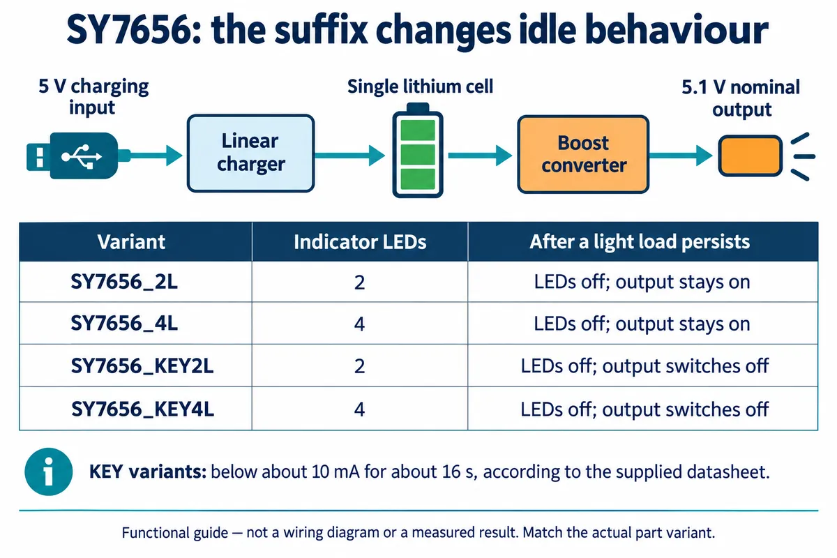
Other SY7656 variants keep their output on when the indicator lights turn off. You therefore need the full variant on the parts list, not just "SY7656".
For a device that must wake itself, test the real idle current and the real wake-up sequence together. If the supply has already switched off, firmware on the unpowered controller cannot run its next scheduled task. A deliberate button-operated restart may still be the right experience, but it needs to be part of the product design.
Second test: check the IP5407 output separately from the lights
The IP5407 module uses the same broad division between battery, charging input and external output, but that does not make its control behavior identical. With the cell connected, pressing the button lit the indicator LEDs. An illuminated level display is not a battery-capacity measurement.
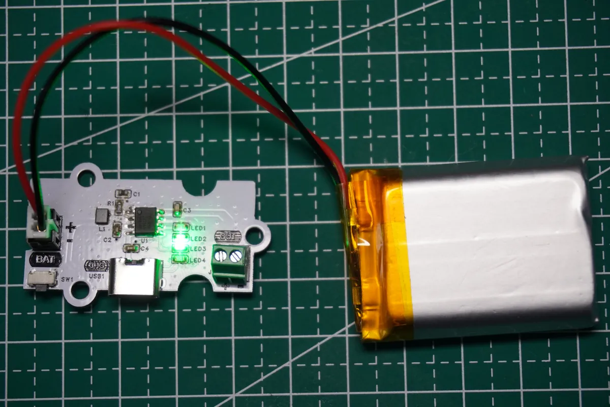
A multimeter at the output terminals read about 5.1 V. That is a useful first check: the module produced a voltage in the expected range. No substantial external load was attached, so it does not establish performance at the rated output current or during a sudden load change.
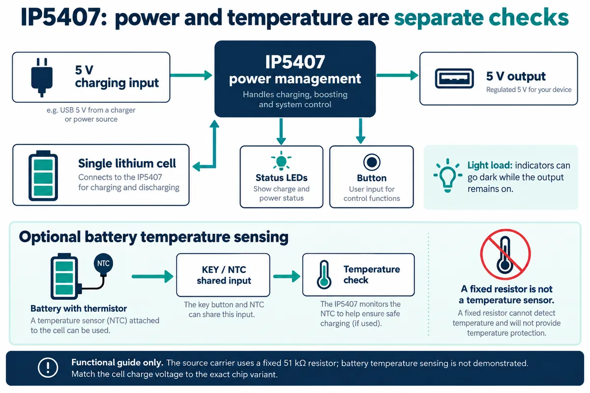
The IP5407 datasheet describes light-load operation in which the indicators turn off after a delay while the output stays at 5 V. Its stated light-load figures are around 50 mA and 36 seconds. Those are manufacturer conditions, not thresholds we measured. They explain why the LEDs alone are an unreliable way to decide whether this board has stopped powering a device. For a prototype that must remain available while idle, that makes the IP5407 approach worth evaluating, with the actual cell, board revision and load changes checked together.
Match the cell and charging behavior before closing the case
A battery's nominal voltage and its charging limit are different specifications. Our cells were 3.7 V nominal lithium-polymer types; the charger must stop at the right final charging voltage. The IP5407 documentation lists a separate 4.35 V variant, and a chip family supporting both voltages does not mean an assembled board identifies either cell type. Confirm the fitted variant and the cell's charging requirements.
Temperature protection needs the same attention. The IP5407 supports an NTC thermistor, a resistor whose value changes with temperature. This carrier instead fits a fixed 51 kΩ resistor on that shared input. That is not a sensor on the battery and cannot measure the cell's temperature.
These checks affect the enclosure too. The charging socket and button must stay accessible, the battery needs secure mounting, and the wiring must not be trapped when the case closes. Our bench assemblies were open, so they say nothing about the temperature inside your case. Also note that the output terminal is separate from the USB-C charging socket; neither a USB-C socket nor a nominal 5 V output means USB Power Delivery support.
Turn the demonstration into a useful power test
Repeat the basic checks first: polarity, startup, button operation, charging and output voltage. Then use the actual controller, display and other loads that will go into the prototype.
- Leave the device in its intended idle state for longer than the supply's documented low-load delay. Record separately whether the LEDs go dark, whether the output remains present, and whether the next user action works. Repeat at different charge states.
- Exercise the largest normal load changes, such as a display waking, a radio transmitting or a motor starting. Watch the voltage at the receiving board and record any restart.
- Insert and remove the charging cable during operation as its own test case. Support for charging while supplying a load does not prove your application sees an uninterrupted transition.
- Measure runtime last, through a representative pattern of active and idle use. Efficiency varies with battery voltage and load, so a headline efficiency figure cannot replace this.
If you use a commercial power bank for early trials, check whether its low-current mode has a time limit. Huawei's instructions for the listed models describe a mode that exits after about two hours. That helps charge a small accessory; it is not the same as leaving a prototype available all day.
The useful outcome is a short description of expected behavior: how the device starts, what stays active while it waits, how it wakes, and what happens when the charger is connected or removed, with measurements from your actual assembly attached. Our bench runs give a starting point; they do not prove battery life or finished-product reliability.