
Your display updates, your button works, and the prototype looks ready to leave the desk. Then you unplug the USB cable and the battery lasts far less time than you expected. Adding a sleep command seems like the obvious fix, but the product still has to wake, restore its connections and do something useful.
For a battery-powered display, handheld controller or sensor, sleep is part of the user experience. A low current reading only matters if the device also responds when it should. On our bench we ran two MicroPython experiments on a Raspberry Pi Pico carrier board, one with machine.idle() and one with machine.lightsleep(), to pull those two questions apart.
First decide what "asleep" means to the user
A controller may need to respond to a button. A room display may need to refresh at intervals. A logger may need to keep accurate time between readings. All three spend most of their lives waiting, but their wake-up requirements differ. Decide what the device must keep doing while it looks off.
The sleep function's name will not tell you the whole product's consumption. In a November 2023 MicroPython discussion, a first-time developer's e-paper temperature display still drew substantial current after calling lightsleep, and the replies pointed at the wireless subsystem and other board-level loads. The useful question is what stays powered in your build.
Our setup was a Pico on a carrier board running MicroPython v1.23.0. Results on other boards, including RP2350-based ones, and on later firmware need their own measurements. Keep the board model and firmware version with every reading.
Give waking up its own button
The wake input is the carrier's user button on GP22. A 10 kohm resistor pulls the line up to 3.3 V when the button is released; pressing it pulls the line to ground. The code listens for that high-to-low transition, a falling edge.
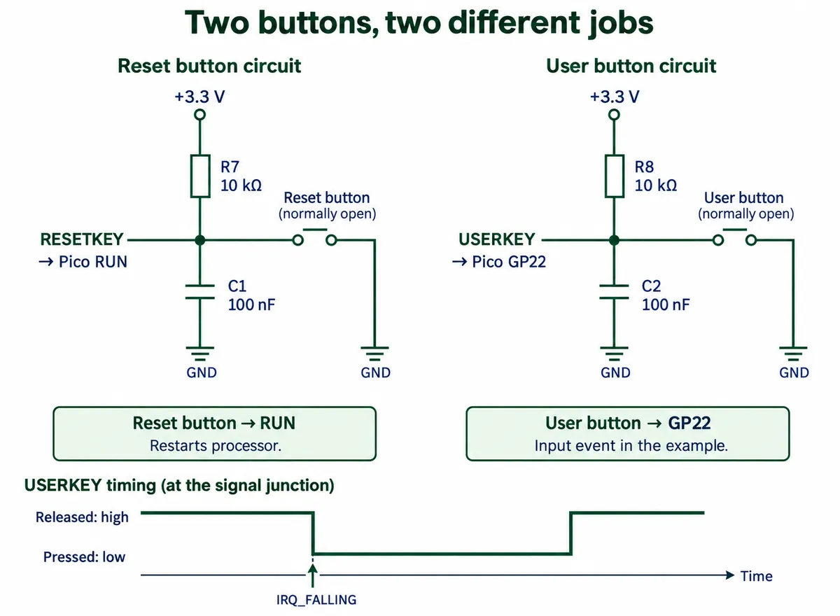
The reset button next to it does a different job. It drives the Pico's RUN pin and restarts the processor, so pressing it says nothing about whether your sleeping application recovered its state. That matters when both buttons end up in an enclosure, or in a tester's hands. The 100 nF capacitor is part of the circuit, but it is no guarantee that every press produces exactly one software event.
The idle experiment checks the input path
The first program configured GP22 as an input with a pull-up, registered a falling-edge handler, and drove the LED on GP25. The handler toggled the LED and printed a message. The main loop looked like this:
button_pin = machine.Pin(22, machine.Pin.IN, machine.Pin.PULL_UP)
button_pin.irq(trigger=machine.Pin.IRQ_FALLING, handler=button_handler)

while True:
    machine.idle()
    print("System is idling...")
    time.sleep(1)
The loop kept printing between presses. idle() does not switch the whole board off until the button is pressed. Our log confirms that the input handler ran, and that is all it shows; it is not a record of uninterrupted deep sleep.
A USB meter read 0.016 A while idling and 0.019 A in normal operation. That is a modest change under our conditions. The supply voltage also differed between the two readings, and we have no figures for the meter's accuracy or repeatability, so this is not a battery-life result.
Then check whether the application comes back
The second program called machine.lightsleep(100000), requesting up to 100,000 ms (100 seconds), after setting up the same button handler. We watched the result on UART0 (GP0 and GP1, 115200 baud) through the carrier's separate CH340K USB-to-serial bridge:
# UART0 and the GP22 button handler are already configured.
machine.lightsleep(100000)
time.sleep(1)
uart.write("Woke up from lightsleep mode.\r\n")
The UART reported the button event and the wake-up message, while the native USB console stayed quiet. That separates "the processor resumed" from "every communication path is working again." For a real display or controller, add the next useful action to the check: read a sensor, refresh the screen, or send and receive one application message.
Two cautions. The program sleeps once; later presses still run the handler, but nothing puts the board back to sleep, so a repeated sleep cycle has to be written explicitly. And the second USB cable powering the serial bridge is a supply path too. Know exactly which path your meter covers before calling a reading the whole product's total.
Do not turn older observations about USB behavior or a 127-second sleep limit into a specification for current boards. The MicroPython v1.26.0 RP2 port source has a hardware-alarm path for timed light sleep and conditional handling of the USB clock. That shows the behavior depends on the version, not that your assembled prototype will always wake. Test the exact firmware and board you plan to ship.
A zero on the USB meter is not a battery-life result
The meter read 0.018 A in normal operation and 0.000 A during light sleep. A meter showing zero has not shown zero current. Without its low-current accuracy and resolution, the reading cannot support any microamp sleep figure.
It also misses the energy spent waking, reconnecting and doing the work. A device that saves energy between updates can still spend too long reconnecting, or wake far more often than intended. Repeated presses, a noisy input, retries and a peripheral left running all belong in the full cycle test.
For the next revision, record three things together: current over a complete cycle, the event that woke the device, and whether its next task succeeded. Start with the existing board, then repeat with the display, sensors and other loads connected. Use a measurement setup that can handle both the low standby current and the short active peaks.
Turn the demonstration into an acceptance check
Write the requirement in terms a tester can check, for example: "after waiting, pressing the user button restores the display and shows a fresh reading." Add your own response-time and battery targets; our bench work sets neither. Test scheduled wake-up separately if the product needs it.
Run the sequence over enough cycles and conditions to expose failures in real use: without the development computer attached, with repeated wake events, and after a reset. Record failures instead of counting an LED flash as proof that the whole device is ready. If cutting power entirely would be simpler, first decide how the product will keep its settings, keep time and start up again.
What we showed is a button input, two ways of waiting, visible meter readings, and a communication path that did not come back by itself after waking. The engineering task now is to make those pieces work together in your product.