
The sensor responds when you shine a flashlight on it. The numbers change, the wiring works, and the prototype is ready for a case. Then the industrial design arrives: a dark front panel, a small opening and a sensor tucked behind it. The electronics have not changed, but the light reaching them has.
For a team building a room monitor, an installation or a portable device, that is worth answering before ordering several enclosures. Can the assembled product still tell apart the conditions that matter? If it displays a lux value, what supports that number after the light has passed through the cover?
On our bench we ran two GraftSense ambient-light modules, a TSL2561 and a MAX44009, from a GraftPort carrier with a Raspberry Pi Pico in MicroPython, and recorded their response to a flashlight. Neither run tested an enclosure window. They give us a baseline for a focused comparison with the intended case.
Decide what the reading is for
A device that tells a dim room from a bright one needs a repeatable input. A device that reports room illuminance in lux needs a stronger basis for the value it shows. Lux expresses light falling on a surface, weighted roughly for human vision. The sensor measures at its own location, which may be behind a cover rather than out in the room.
The question comes up often. In an Arduino Forum discussion from late 2018, a novice building a weather station asked how small light-sensor boards could be protected and still work. One respondent described using a dome while caring mainly about patterns, not calibrated lux values.
For your first enclosed prototype, write down the decision the reading must support, for example "recognize whether the installation is in its dim or bright operating condition." If you instead need comparable lux values between locations, plan a comparison with a suitable reference instrument. Those two requirements lead to different acceptance tests.
Establish the uncovered baseline with the TSL2561
The TSL2561 module connected with SDA on GPIO4 and SCL on GPIO5. Its address selector supports 0x29, 0x39 or 0x49, and our scan found 0x39. Use the actual jumper position and wiring, including a common ground and compatible signal levels.
We used a 402 ms integration time and 1× gain. Integration time is how long the sensor collects light for one measurement; gain changes sensitivity. Keep both with your log, because a number without its measurement settings is hard to compare later.
The sensor has two optical channels: one responds to visible plus infrared light, the other mostly to infrared. The driver combines them to estimate lux. That matters for a tinted window, because changing which wavelengths reach the sensor can matter as much as reducing the overall amount of light.
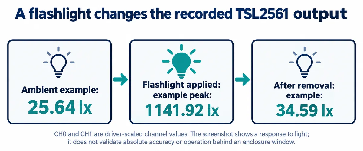
The readings rose under the flashlight to a peak of 1141.92 lx and fell again afterwards. That shows the setup responds to changing light. It does not show agreement with a reference meter, behavior in direct sunlight or accuracy behind a dark panel.
Two details matter when extending this. First, the driver's raw-read method scales both channels by 16 at 1× gain, so the printed CH0 and CH1 values are not untouched register counts. Second, the lux call takes a fresh reading, so the printed channels and lux need not come from the same acquisition while the light is changing.
Stay with the 402 ms setting while you establish a baseline. The driver's lux calculation does not compensate for the shorter integration settings, and the TSL2561 datasheet gives package-specific coefficients and describes its formulas for open-air use. A new gain, timing, package or optical path deserves its own check.
The MAX44009 gives a second baseline, not a winner
The MAX44009 module used the same controller pins. It has two addresses, 0x4A and 0x4B, and our scan found 0x4B. Its driver credits Mike Causer's MIT-licensed micropython-max44009.
The program enabled continuous conversion and automatic range selection. It also wrote an integration-time field, but in automatic mode the sensor chooses the integration time itself, so this was not a fixed 100 ms measurement.
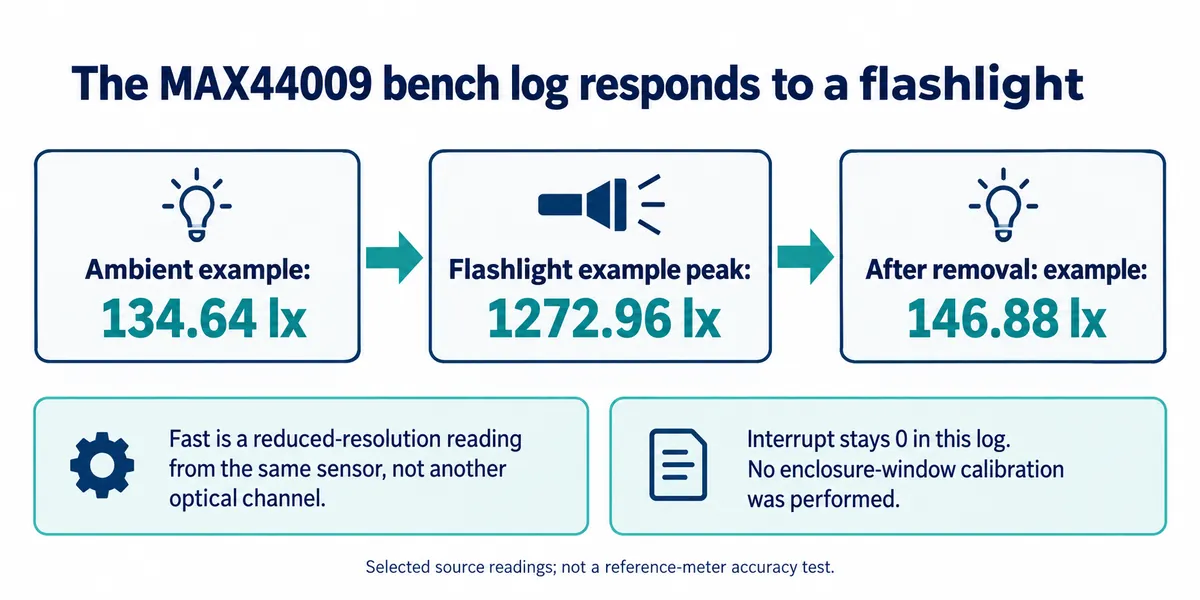
The output rose from about 134.64 lx to a peak of 1272.96 lx under the flashlight and fell again. This was a separate run from the TSL2561 test, so the two sets of readings cannot tell you which sensor is more accurate without the same illumination, geometry and a reference measurement.
The column labeled "Fast" is a lower-resolution readout from the same sensor, taken from the high-byte register alone, not a second optical channel. The full readout adds more mantissa bits. The conversion factors 0.72 and 0.045 belong to those two representations and are not interchangeable calibration constants. The MAX44009 datasheet also specifies an overrange indication; before relying on outdoor readings, make sure the software handles it and reads both registers using the documented transaction sequence. Our bench output does not cover those edge cases.
Compare the cover with the sensor held still
Now introduce the material you intend to use. Keep the sensor and light source in the same positions, record an uncovered reading, then place the candidate window over the sensor and record again once the reading settles. Repeat at the final mounting depth. Moving the lamp while adding the cover mixes two changes into one result.
Texas Instruments' Ambient Light Sensor Application Guide describes this comparison and explains how window transmission and opening geometry affect the optical design. Its dimensions belong to TI's own sensors, so use the principle to plan a test rather than copying a window size.
If the covered reading is consistently lower, the uncovered-to-covered ratio can be a starting point for compensation. It is still a result for the tested material, geometry and lighting. Repeat it under the light sources your product will meet, and compare with a reference if you need defensible lux values. A larger software multiplier does not recover information lost to noise or saturation.
A small opening can also change how the sensor responds to light from the side. Test the assembled shape at relevant orientations instead of always holding the light directly above it. Check that the sensing area, not just the center of the board, lines up with the opening, and inspect any adhesive, protective film or decorative coating over the window.
Keep a small record that the next build can repeat
For each candidate, save the board and driver version, sensor address, measurement settings, cover material, mounting distance and the uncovered and covered readings, plus a photo of how lamp, sensor and cover were held. If a result looks wrong, you then have something to reproduce instead of another round of random code changes.
Run the comparison across the intended range: dim, normal and bright. Then try the assembled product with its own indicators and display off and on, because a case can let internal light reach the sensor even when the room has not changed. We have not run these enclosure tests yet.
For a small batch, keep the same window specification and check whether assembled units agree closely enough for the product's purpose. Define "closely enough" from the user decision you wrote down at the start. A dim-or-bright detector and an illuminance logger should not share a tolerance just because both print "lx".