
You move a working button-and-light demo to another board. The program runs, but the light goes dark when the code says on(). Or the button appears pressed whenever nobody is touching it. Before rewriting the interaction, check how the new hardware represents "active."
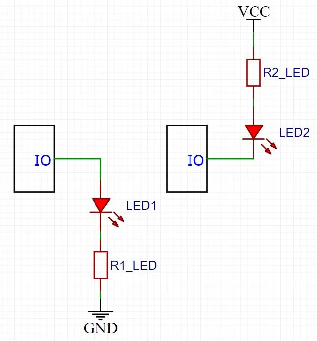
For a team building a small control panel, the desired behavior is simple: a press should mean a press, and an illuminated indicator should mean what its label says. The voltage used to produce that behavior can change between boards. Keeping those two ideas separate makes the next prototype easier to understand. We use MicroPython's Signal class for this, and the circuit shows why: two ordinary LED connections need opposite output levels.
The light is not reading the name of your function
A GPIO pin is a general-purpose electrical connection. In ordinary output mode, MicroPython's Pin.on() drives it high and Pin.off() drives it low. Whether either action lights an LED depends on the surrounding circuit. Active-low means the device becomes active when the controlling signal is low; it does not mean the program or the LED is defective. The schematic above shows topology only; component values and operating limits still depend on the circuit.
This confuses real users. In a MicroPython discussion dated March 14, 2025, a developer reported that the built-in LED on a LOLIN D1 mini behaved opposite to the method names. The accepted reply explained the wiring and pointed to Signal. That board is an example of the issue, not a pin assignment to copy.
A button uses the same idea on an input. A pull-up holds the input high while the button is released; pressing a correctly connected button brings it low. With inversion enabled, the application can read that low level as "pressed." Check the actual connector and schematic first: software inversion cannot fix a button connected to the wrong pin.
Put the board difference in one place
In our bench setup, a WIZnet W5100S-EVB-Pico sat on a GraftPort-Pico-ETH v1.1 carrier, with the user button on GPIO26 and the LED on GPIO25. The button input is inverted; the LED output is not. The application logic then asks whether the button is active, rather than repeatedly asking whether the voltage is low.
Here is the essential setup, with the initial LED value made explicit. These pins match that arrangement; confirm your board's wiring and firmware before running it.
from machine import Pin, Signal

button = Signal(Pin(26, Pin.IN, Pin.PULL_UP), invert=True)
led = Signal(Pin(25, Pin.OUT, value=0), invert=False)

print("Pressed:", bool(button.value()))
led.on()   # Activate the configured LED signal.
led.off()  # Deactivate it.
If a replacement board has an active-low LED, its configuration needs invert=True and an appropriate inactive initial pin level. The rest of the application can keep saying led.on(). The MicroPython Signal reference describes this mapping; wrapping an existing Pin is the portable construction pattern. This is a way to describe a known circuit, not a substitute for identifying it.
What the test program does
The program remembers the previous button state. When the logical value changes from released to pressed, it flips an LED state variable, writes that state to led and prints the result. On the console, a prompt to press the button is followed by lines alternating between ON and OFF.
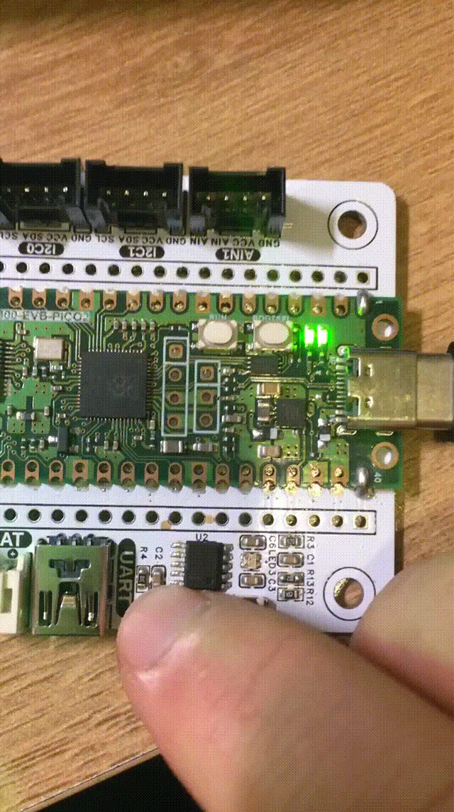
The recording above comes from the earlier plain-GPIO version of the same button-and-light exercise; it shows the physical behavior, not proof of which firmware or code was running. The short delays in the loop make it a simple polling demonstration. They do not establish that every switch press will be captured under all workloads.
The useful change is in the code's meaning. A physical falling edge at the active-low button becomes a rising logical "pressed" state after inversion. That matters when someone later adds an interrupt: the edge selected on the underlying pin still needs to match the wiring. Do not choose it from the application's boolean name alone.
Confirm the behavior at the panel
Before handing over the revised prototype, check a released button, a held button and several separate presses. Confirm the physical light as well as the console message. Then restart the board and observe the indicator before, during and after the program starts. Initializing a Python object does not describe what the hardware does before that code runs.
Keep a short mapping beside the board configuration:
- connector or GPIO;
- input or output;
- active level;
- the user-visible meaning, such as "button pressed" or "ready light illuminated."
Those labels are clearer than two unexplained zeroes. Record any changed board revision so a colleague does not restore the old polarity while troubleshooting.
An Arduino forum thread from September 16, 2026 shows the limit of this approach. The user had already named active-low relay states correctly, yet the reported contact behavior remained wrong; the discussion moved to wiring, power and measurement, and the visible thread does not establish a final cause. Correct naming helps you investigate. It does not prove the connected device is working.
For an indicator-and-button prototype, the next step is small and testable: make the electrical-to-logical mapping explicit, then check what a person actually sees and does. Treat debounce, electrical compatibility and startup behavior as separate checks rather than expecting one inversion flag to solve them all.