
You have chosen a controller for your prototype, and a module already does the job you need. Then you notice that one is described as 3.3V and the other as 5V. Can you connect them, or do you need another board in between?
The answer depends on more than the supply label. A July 2026 question from someone starting with ESP32 asks whether familiar Arduino sensor modules will work with the new controller. It captures the practical problem: you want to combine available parts without discovering an electrical mismatch after the prototype is assembled.
On our bench we connected a small GraftSense level-converter board to a GraftPort-RP2040 controller. The setup is useful for seeing where an adapter fits, but we did not record signal levels or timing with it. This note uses it to separate the decisions that need checking before you adopt a mixed-voltage connection.
Separate the module's power from its signal
A supply connection provides energy to the module. A signal connection carries information, such as a high or low state or a sequence of data bits. A board may accept a 5V supply while using a different voltage for its signals. Conversely, powering a controller through USB does not establish that its GPIO inputs can accept 5V.
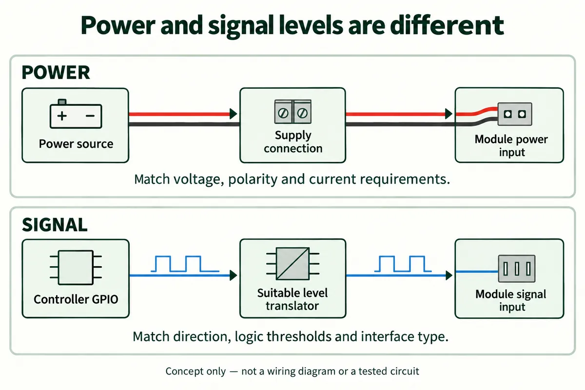
For each connection, identify the supply voltage, the signal's output range and the receiving pin's allowed range. As Texas Instruments explains, a signal also has to be high enough to count as a logical 1, not merely low enough to avoid exceeding a limit. Use the specifications of the exact devices rather than a universal rule that all 5V modules accept, or reject, 3.3V signals.
If an interface needs translation, that translation must suit the kind of signal. A one-direction control line, a two-way I2C bus and a fast serial interface do not impose the same requirements. Choosing a small board marked "level converter" is only the beginning of that check.
Look at what the adapter actually provides
The converter board we used has connectors marked LV and HV, for the low- and high-voltage sides, and separate signal markings. Its circuit uses a 2N7002 MOSFET on one signal path and a 1N5819WS diode on the other. It is not simply a cable with differently shaped plugs.
The intended arrangement carries one signal from the controller toward the peripheral and another back toward the controller. That allows communication in both directions overall; it does not mean that either individual channel can be used freely in either direction. The board's documentation explicitly excludes it from I2C use. Keep that restriction when choosing an adapter for a shared sensor bus.
The documentation also needs reconciling before anyone copies the design. Its input and output pin descriptions conflict between sections. Its schematic labels a low-voltage rail as 3.3V while naming an XC6206P302MR regulator, and Torex lists that part variant as 3.0V. Resolve the fitted part and connector mapping against the actual board. Our setup is a connection example, not a ready-to-copy pinout.
For a new prototype, a useful handoff is a small table listing each signal's source, destination, direction and electrical requirements. Put power in a separate row. This prevents "the low-voltage side" from being mistaken for a promise about every pin on that connector.
What our bench setup showed, and what it did not
We connected the adapter to the controller's DIO1 connector through a four-wire cable, then added a small module on the far side, which lit its blue LED when powered.
That arrangement shows the physical fit and that the downstream module received power. It does not show a voltage measurement, an oscilloscope trace or a recorded communication exchange. We ran no program for this setup, so the lit module is not proof of a particular command, data rate or working return channel.
The adapter itself does not require a software driver to change a voltage level. The connected devices may still need software to send and interpret information. Keeping those two facts separate avoids the misleading conclusion that "no adapter code" means the complete system is automatically working.
Make the next test answer the compatibility question
Once the pin mapping and supply details are settled, test a simple known signal in each intended direction. Check the receiving side's high and low levels against its specifications, then repeat with the real communication pattern and load. A correct static voltage alone cannot establish that fast transitions will arrive clearly.
Also test startup and the normal power sequence. If one board powers up before the other, record what reaches the unpowered side. These are checks we have not yet run on this setup; they define the evidence needed before an adapter becomes part of a prototype handed to other people.
If your next addition is an I2C sensor, keep voltage compatibility separate from the address question. Even electrically compatible modules may share the same fixed address, which no level converter will fix.
Choose the simplest compatible combination
Sometimes the cleanest first version uses a peripheral already compatible with the controller's signals. Sometimes an existing 5V module is worth keeping and a suitable translator is the right addition. Make that decision from the actual interfaces and the work the prototype needs to demonstrate, rather than from connector appearance alone. Write down the exact board versions and the connections you intend to make; that list is the starting point for any review before you commit to the enclosure or a larger batch.